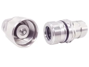
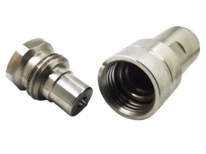
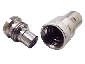
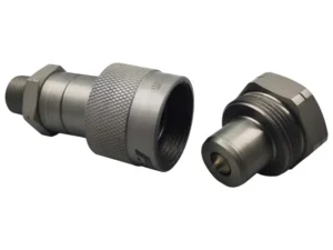
Guide to Safe Installation of Quick Couplings
Before starting the installation process, it is important to understand the specific type of Quick Coupling being used. Read and familiarize yourself with the manufacturer’s instructions, as different couplings may have varying installation methods.
Before installation make sure that the selected quick connect coupling is suitable for the fluid to flow through it and the surrounding atmosphere, with respect to its design (series), materials, seals, working pressure and working temperature.
This safety guide provides instructions for selecting and using (including installing, connecting, disconnecting, and maintaining) Quick Coupling products and related accessories. This safety guide is a supplement to and is to be used with, the specific publications for the specific Quick Coupling products and related accessories being considered for use.
Pressure
quick connect couplings selection must be made so that the published rated pressure of the coupling is equal to or greater than the maximum system pressure. Pressure surges in the system higher than the rated pressure of the coupling will shorten the quick connect coupling’s life. Do not confuse burst pressure or other pressure values with rated pressure and do not use burst pressure or other pressure values for this purpose.
Fluid compatibility
quick connect couplings selection must assure compatibility of the body and seal materials with the fluid media used. See the fluid compatibility chart.
Body Materials
Seal Material
Temperature
be certain that fluid and ambient temperatures, both steady and transient, do not exceed the limitations of the quick connect couplings. Use caution and hand protection when connecting or disconnecting quick connect couplings that are heated or cooled by the media they are conducting or by their environment.
Size
transmission or power by means of pressurised liquid varies with pressure and rate of flow. The size of the quick connect couplings and other components of the system must be adequate to keep pressure losses to a minimum and avoid damage due to heat generation or excessive fluid velocity.
Pressurised connection or disconnection
if connecting or disconnecting under pressure is a requirement, use only quick connect couplings designed for that purpose. The rated operating pressure of a quick connect coupling may not be the pressure at which it may be safely connected or disconnected.
Environment
care must be taken to ensure that quick connect couplings are either compatible with or protected from the environment (that is, surrounding conditions) to which they are exposed. Environmental conditions including but not limited to ultraviolet radiation, ozone, moisture, water, salt water, chemicals, and air pollutants can cause degradation and premature failure.
Locking means
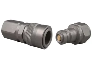
ball locking quick connect couplings can unintentionally disconnect if they are dragged over obstructions on the end of a hose or if the sleeve is bumped or moved enough to cause disconnection. Sleeves designed with flanges to provide better gripping for oily or gloved hands are especially susceptible to accidental disconnection and should not be used where these conditions exist. Sleeve lock or union (threaded) sleeve designs should be considered where there is a potential for accidental uncoupling.
Mechanical loads
external forces can significantly reduce quick connect couplings’ life or cause failure. Mechanical loads which must be considered include excessive tensile or side loads and vibration. Unusual applications may require special testing prior to quick connect couplings selection.
Specifications and standards
Welding and brazing
heating of plated parts, including quick connect couplings and port adapters, above 450 °F (232 °C) such as during welding, brazing, or soldering may emit deadly gases and may cause coupling seal damage.
Pre-installation inspection
before installing a quick connect coupling, visually inspect it and check for correct style, body material, seal material, and catalogue number. Before final installation, coupling halves should be connected and disconnected with a sample of the mating half with which they will be used.
Quick connect coupling halves from other manufacturers
if a quick connect coupling assembly is made up of one AKJia half and one half from another manufacturer, the lowest pressure rating of the two halves should not be exceeded.
Fitting installation
use a thread sealant, when assembling taper pipe thread joints in quick connect couplings. Be sure the sealant is compatible with the system fluid or gas. To avoid system contamination, use a liquid or paste type sealant rather than a tape style. Use the flats provided to hold the quick connect coupling when installing fittings. Do not use pipe wrenches or a vice on other parts of the coupling to hold it when installing or a removing fittings as damage or loosening of threaded joints in the coupling assembly could result. Do not apply excessive torque to taper pipe threads because cracking or splitting of the female component can result.
Caps and plugs
use dust caps and plugs when quick connect couplings are not coupled to exclude dirt and contamination and to protect critical surfaces from damage.
MAINTENANCE
Even with proper selection and installation, quick connect coupling life may be significantly reduced without a continuing maintenance program. Frequency should be determined by the severity of the application and risk potential. A maintenance program must be established and followed by the user and must include the following as a minimum:
Visual inspection of quick connect couplings
any of the following conditions require immediate shut down and replacement of the quick connect coupling:
- Cracked, damaged, or corroded quick connect couplings parts.
- Leaks at the fitting, valve or mating seal.
- Broken coupling mounting hardware, especially breakaway clamps.
Visual inspection all other:
- Leaking seals or port connections.
- Excess dirt build-up on the coupling locking means or on the interface area of either coupling half.
- Defective clamps, guards, and shields.
- System fluid level, fluid type and any entrapment.
Functional test
operate the system at maximum operating pressure and check for possible malfunctions and freedom from leaks. Personnel must avoid potential hazardous areas while testing and using the system.
Replacement intervals
specific replacement intervals must be considered based on previous service life, government or industry recommendations, or when failures could result in unacceptable downtime, damage or injury risk.
